Bernoulli's Principle & Scientific Background Research
A deep-dive research paper on Bernoulli's Principle — the experimental setup, the fluid dynamics theory, why the classic blowing-paper demo actually violates Bernoulli's assumptions (viscous entrainment & Coandă effect), and its real engineering applications in aviation.
SYSTEM LOG // BERNOULLI_PRINCIPLE
Overview
This Research is About Bernoulli’s Principle and his Scientific Background and History made by Asaad Zein as a researcher in aerospace minds club and this week of research is about “If you hold two sheets of paper and blow gently between them, why do they pull together instead of pushing apart? (Bernoulli’s Principle)”
Experimental Setup & Protocol
- Aim: Observe physical behavior when air is blown between two parallel sheets of paper and identify the governing fluid dynamics.
- Procedure:
- Hold two sheets of paper vertically so they are parallel with a small air gap between them.
- Blow air steadily into the space between the two sheets.
- Observation: The two papers move inward toward each other instead of pushing apart.
Bernoulli’s Principle and Its Scientific Background
Bernoulli’s principle is a law of physical science that explains the relationship between a fluid’s pressure and velocity. The word fluid may refer to either a liquid or a gas. When the velocity of a fluid increases, its pressure decreases. Conversely, when the velocity of a fluid decreases, its pressure increases. Developed by Swiss scientist Daniel Bernoulli who published it in his book Hydrodynamica in 1738, this principle is readily observable in many real-world scenarios and has many practical applications. Most notably, the Bernoulli principle is an underlying concept in the science of flight. Moreover, the discovery of Bernoulli’s principle was essential to the emergence of hydrodynamics, or the science of the motion of fluids, as a unique field of study.
Bernoulli’s principle states that an increase in the speed of a fluid occurs simultaneously with a decrease in pressure or a decrease in the fluid’s potential energy. Although Bernoulli discovered that pressure decreases when the flow speed increases, it was actually Leonhard Euler who created Bernoulli’s equation that we use today in 1752.
Bernoulli’s principle can be derived from the principle of conservation of energy. This states in a steady flow, the sum of all forms of energy in a fluid will be the same at all points of that streamline. While all the energy remains constant, an increase in the speed of the fluid will imply there is an increase in the dynamic pressure (kinetic energy). This happens with a simultaneous decrease in the potential energy including the static pressure and internal energy.
Bernoulli’s Equation in Aerodynamics
For incompressible, inviscid, and steady flow at a constant elevation (z₁ = z₂), the relationship between static pressure and dynamic pressure along a streamline is expressed as:
p + (1/2) ρ v² = p₀ (Total Pressure / Constant)Where:
- p = Static pressure (Pa)
- ρ = Fluid density (kg/m³)
- v = Flow velocity (m/s)
- (1/2) ρ v² = Dynamic pressure (Pa)
- p₀ = Total (stagnation) pressure (Pa, constant along a streamline)
In this form, as the local flow velocity (v) increases, dynamic pressure increases, forcing static pressure (p) to decrease to maintain a constant total pressure (p₀).
Bernoulli’s equation over the streamline
P_s + (1/2) ρ V² + ρ g h = Constant along a streamlineThis is Bernoulli’s Equation, which expresses the principle of conservation of energy for an ideal, incompressible, and frictionless fluid flowing along a streamline.
Each term represents a form of pressure or energy per unit volume:
(P_s) (Static Pressure): The actual thermodynamic pressure of the fluid. It represents the potential energy associated with pressure forces.
((1/2) ρ V²) (Dynamic Pressure): The pressure due to fluid motion. It represents the kinetic energy per unit volume, where ρ is the fluid density and V is the fluid velocity.
(ρ g h) (Hydrostatic Pressure): The pressure due to gravity. It represents the potential energy per unit volume due to height, where:
- g is the acceleration due to gravity.
- h is the height or elevation above a reference level.
Bernoulli’s Principle Demonstrations
- Most Common One The Blowing paper (why it is kinda don’t really have anything to do with Bernoulli’s principle)
- The Soda Cans demonstration (that shows how high speed fluid causes the cans to hit each other due to low pressure)
- The Ping Pong ball Cone stunt (It shows how the ping pong ball is staying up due to the pressure)
Let’s Return to First Demonstration and why it is kinda don’t really have anything to do with Bernoulli’s principle it is because if we looked at how does our mouth and the air jet stream is coming out of our mouth and it pressure in this explanation from very cool channel LightAndSportyGuy in this video ”Myth: Blowing over a sheet of paper demonstrates Bernoulli’s Principle”
Why the Paper Demonstration Violates Bernoulli’s Principle
The 4 Strict Constraints of Bernoulli’s Equation
- Inviscid Flow (μ = 0): Zero fluid friction.
- Steady Flow (∂v/∂t = 0): Velocity at any point is time-invariant.
- Incompressible Flow (ρ = const): Constant density.
- Single Streamline: Total energy constant p₀ applies only along a continuous streamline.
The Moving Air Fallacy & Open-Air Counterexample
A common misconception states that “moving air travels faster, so its pressure is automatically lower than stationary air.” However, simply blowing air into an unconfined open space using your mouth or a hair dryer does not drop its static pressure below atmospheric pressure (p_atm). Free jets exit into ambient air at approximately atmospheric pressure. Bernoulli’s theorem represents total energy conservation along continuous streamlines within a fluid — it cannot be naively applied to compare a forced air stream directly with surrounding stationary room air across disjoint boundaries.
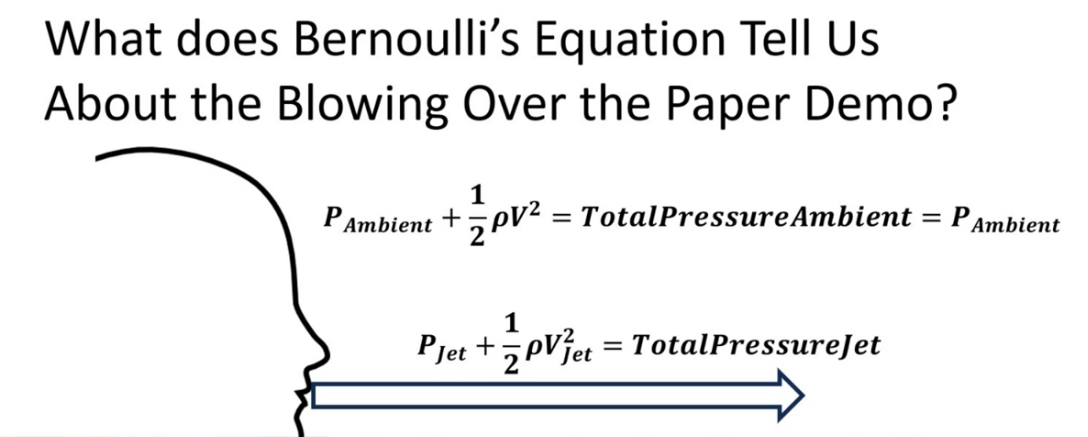
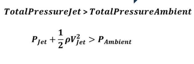
And this explains that the demonstration of us blowing on the paper and it is rising is just not supported by Bernoulli’s principle but on Viscosity
What is Viscosity and how does this work and isn’t really Bernoulli’s principle that makes the paper rise?
Viscosity is a fluid’s internal resistance to flow. And this works because in an ideal fluid, with no viscosity, when the jet starts, it would have to move some of the ambient fluid out of the way. But Bernoulli’s equation only applies to steady state flow — ignoring any transient effects. Then, in an ideal fluid (which does not exist in real life), you would have a virtual “tube” of fluid moving through the stationary ambient fluid and nothing really would happen. If the paper moves, then energy was transferred and not conserved — contrary to the assumptions used to derive Bernoulli’s equation.
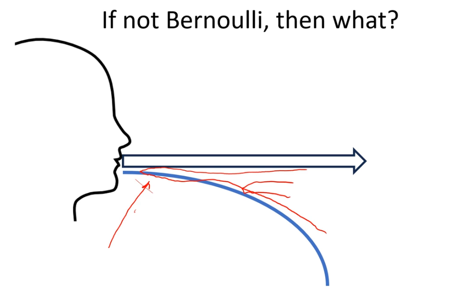
True Mechanism: Viscous Entrainment, Boundary Layer Constriction & Coandă Effect
When air is blown over a paper, viscosity (μ ≠ 0) cannot be ignored. As explained by University of Leeds Fluid Dynamics, viscosity is a fluid’s internal resistance to shear flow.
- Boundary Layer Formation & Passageway Constriction: Internal surface friction forms a thin, slow-moving boundary layer along the surface of each paper sheet. These slow-moving layers take up physical space inside the narrow gap. As a result, the effective central passageway becomes narrower. By mass conservation continuity (ṁ = ρ A v), forcing air through this constricted central space accelerates the central flow velocity, dropping static pressure between the sheets relative to external atmospheric pressure.
- Viscous Entrainment: The high-velocity jet leaving the mouth drags surrounding stationary air molecules along with it due to shear stress, creating a localized low-pressure zone.
- Coandă Effect: The air jet follows the surface curvature of the paper, deflecting outward and creating an upward/inward reaction force.
- Disjoint Streamlines: The moving air jet and static room air represent different streamlines with different total pressure constants (p₀), invalidating direct cross-streamline calculations.
Applications, Airplane Wings & Future Developments
Engineering Applications of Inviscid Flow Principles
While classroom paper demonstrations often violate inviscid assumptions due to viscous boundary layer entrainment and shear stress, controlled engineering systems leverage Bernoulli’s energy conservation equation under streamlined conditions:
Venturi Flow Meters & Internal Hydraulics: By introducing a smooth constriction in a pipe of cross-sectional area A₁ to A₂ (where A₂ < A₁), fluid continuity forces mass velocity to increase (ṁ = ρ A₁ v₁ = ρ A₂ v₂). Assuming incompressible flow (ρ = constant), Bernoulli’s equation establishes the pressure drop across the throat:
Δp = p₁ − p₂ = (1/2) ρ (v₂² − v₁²)Measuring Δp yields precise volumetric flow rates without moving mechanical parts.
Pitot-Static Systems in Avionics: Aircraft measure airspeed by comparing total pressure (p₀) collected at the forward-facing stagnation point (v = 0) with static pressure (p∞) sampled perpendicular to the flow along the fuselage. Applying Bernoulli’s equation along the stagnation streamline yields true airspeed:
v∞ = √( 2(p₀ − p∞) / ρ∞ )Atomization & Carburetion: High-speed airflow past a fuel nozzle creates a localized static pressure reduction below ambient atmospheric pressure (p_local < p_atm). Atmospheric pressure acting on the fuel reservoir forces fluid up the tube, where high shear forces at the nozzle interface break the liquid stream into fine droplets.
Aerodynamic Lift: Deconstructing Misconceptions via Fluid Dynamics
The application of Bernoulli’s principle to airfoil lift is frequently misstated in introductory physics. A rigorous aerodynamic evaluation requires distinguishing classical myths from complete mathematical continuum mechanics:
1. The Equal Transit Time Fallacy vs. Physical Reality
- The Fallacy: The claim that air parcels split at the leading edge must rejoin simultaneously at the trailing edge, forcing air over the longer upper camber to travel faster.
- The Physical Reality: Experimental smoke-tunnel visualization and computational fluid dynamics (CFD) prove that air over the upper surface reaches the trailing edge much faster than air underneath. The upper parcel arrives well before the lower parcel, rendering equal transit time physically invalid.
2. Coupled Pressure and Circulation Field (Kutta-Joukowski Theorem)
Lift is generated by a net static pressure differential integrated over the airfoil planform area (S):
L = ∮ (p_lower − p_upper) dAWhile Bernoulli’s dynamic pressure relationship (p + (1/2) ρ v² = p₀) accurately describes local pressure drops where local flow velocity increases, the velocity field itself is governed by bound circulation (Γ). According to the Kutta-Joukowski theorem for two-dimensional inviscid flow:
L′ = ρ∞ V∞ ΓWhere Γ = ∮ v · ds represents the net line integral of velocity around the closed contour of the airfoil.
3. Newton’s Third Law & Momentum Deflection
Pressure integration (Bernoulli) and momentum conservation (Newton) are dual descriptions of the same continuous fluid flow:
- The asymmetric pressure gradient accelerates fluid downward over the upper camber, imparting downward momentum to the air mass (downwash angle α).
- By Newton’s Third Law (F = dp/dt), the downward force exerted by the airfoil on the air mass creates an equal and opposite reaction force pushing the wing upward.
Advanced Aerospace Research & Future Developments
Modern fluid dynamics research extends far beyond classical steady inviscid assumptions, focusing on active boundary layer control, non-linear vortex dynamics, and computational modeling:
Active Boundary Layer & Circulation Control (CCW)
- High-Lift Coandă Jet Ejection: Blowing high-momentum micro-jets of air over a rounded trailing edge prevents boundary layer separation at extreme angles of attack, artificially inflating circulation (Γ) and increasing the maximum lift coefficient (C_L,max) without mechanical flaps.
- Hybrid Laminar Flow Control (HLFC): Suction porous skins actively evacuate turbulent boundary layer fluid, preserving low-friction laminar flow regimes and minimizing skin friction drag.
High-Performance CFD & Turbulence Modeling
- Direct Numerical Simulation (DNS): Solves the full 3D time-dependent Navier-Stokes equations without turbulence approximations:
ρ ( ∂v/∂t + v · ∇v ) = −∇p + μ ∇²v + f - Reynolds-Averaged Navier-Stokes (RANS) & LES: Industrial aerospace design utilizes Large Eddy Simulation (LES) to model transient vortex shedding, dynamic stall on helicopter rotor blades, and high-speed fighter aircraft maneuvering.
Bio-Inspired Morphing Wings & Unsteady Aerodynamics
- Adaptive Compliant Structures: Modern UAV and next-generation aircraft wings continuously alter camber and twist using shape-memory alloys (SMAs), eliminating discrete hinges to maintain smooth velocity distributions across subsonic, transonic, and supersonic regimes.
Resources & References
Fundamental Aerodynamics & Historical Background
- TecQuipment: Daniel Bernoulli & Equation: Overview of Daniel Bernoulli’s life, his 1738 book Hydrodynamica, and Leonhard Euler’s 1752 mathematical formulation of the Bernoulli equation.
- EBSCO Research Starter: Pressure: Physical definition and thermodynamic properties of fluid static pressure.
- EBSCO Research Starter: Velocity: Scientific analysis of velocity vector fields in fluid dynamics.
- EBSCO Research Starter: Daniel Bernoulli: Biographical profile of Daniel Bernoulli and his major contributions to early physics and hydrodynamics.
- Wikipedia: Hydrodynamica: Historical details regarding Bernoulli’s landmark 1738 treatise that laid the foundation for modern fluid mechanics.
- EBSCO Research Starter: Hydrodynamics: Scientific primer on fluid kinematics, dynamics, and sub-field classification.
- Wikipedia: Leonhard Euler: Biography of Leonhard Euler, highlighting his derivation of the modern differential equations of fluid motion.
- Wikipedia: Bernoulli’s Principle: Comprehensive theoretical background on energy conservation along streamlines in fluid flows.
- Princeton University: Bernoulli’s Equation in Aerodynamics: Derivation of incompressible, steady-state Bernoulli equation for aerodynamic flows at constant elevation.
- NASA Beginner’s Guide to Aeronautics: Bernoulli’s Equation: NASA Glenn Research Center’s formal breakdown of static, dynamic, and hydrostatic pressure terms along streamlines.
Demonstrations & Viscous Flow Physics
- YouTube: Bernoulli’s Principle Demonstrations: Visual collection of classic fluid dynamics classroom experiments and stunts.
- YouTube: The Ping Pong Ball Cone Stunt: Video demonstration illustrating trapped aerodynamic pressure forces supporting a ball in a high-speed funnel jet.
- University of Leeds: Fluid Dynamics & Viscosity: Detailed explanation of fluid shear stress, boundary layer effects, and internal friction (viscosity).
- YouTube: LightAndSportyGuy Channel: Educational physics and aerodynamics channel focused on experimental breakdown and debunking physics misconceptions.
- YouTube: Myth: Blowing over a sheet of paper demonstrates Bernoulli’s Principle: Video analysis by LightAndSportyGuy detailing velocity profiles, shear entrainment, and why the blowing paper demo violates Bernoulli’s assumptions.
- Japan Society of Mechanical Engineers (JSME): Blowing air between two sheets of paper (2011). Explains boundary layer growth and passage narrowing in parallel sheet experiments.
- University of Sydney Physics: Two Sheets of Paper Demonstration. Academic physics activity sheet on fluid properties and pressure differentials.
Textbooks & Academic Courseware
- MIT OpenCourseWare: Advanced Fluid Mechanics (Course 2.25): Massachusetts Institute of Technology. (Open-access graduate lecture series covering inviscid flow theory, potential flow, boundary layer separation, and Navier-Stokes derivations).
- MIT OpenCourseWare: Classical Mechanics - Fluid Dynamics: Massachusetts Institute of Technology. (Public physics course notes detailing ideal fluid dynamics, mass conservation along streamlines, and Bernoulli equation derivations).
- University of Cambridge: Fluid Dynamics Course Resources: Department of Applied Mathematics and Theoretical Physics (DAMTP). (Open mathematical tripos lecture notes on vorticity dynamics, hydrodynamic stability, and ideal fluid kinematics).
Technical Reports & NASA Aerodynamics Portals
- NASA Glenn Research Center: Incorrect Theory of Lift #1 (Equal Transit Time): NASA Beginner’s Guide to Aeronautics. _(NASA educational portal debunking the equal transit time myth through physical pressure integration and flow visualization).*
Special thanks to the LightAndSportyGuy Channel and his video ”Myth: Blowing over a sheet of paper demonstrates Bernoulli’s Principle” for detailing the velocity profiles and debunking this misconception.