Airplanes and Aerodynamics: The Four Forces of Flight
A research paper on how multi-ton metal airplanes stay in the sky — the four forces of flight, airfoil anatomy and lift generation (Bernoulli + Newton), factors affecting lift, drag, ground effect, historical evolution from the Wright Flyer to supersonic jets, and the future of aviation.
SYSTEM LOG // AIRPLANES_AERODYNAMICS
Overview
This is a Research about airplane and aerodynamics made by Asaad Zein for his club aerospace minds as member of the research team in week of Why doesn’t a multi-ton metal airplane fall from the sky? representing this paper that covers:
The Four Forces of Flight: Lift, Weight, Thrust, and Drag, and how their balance dictates aircraft motion.
Aerodynamic Theory & Lift Generation: The anatomy of airfoils, debunking the equal-transit myth, and explaining lift using both Bernoulli’s Principle (pressure differentials) and Newton’s Laws (momentum change/downwash).
Factors Affecting Flight & Fluid Dynamics: Air Viscosity, wing geometries, Angle of Attack (AOA), Ground Effect, and mathematical modeling via the NASA Lift Equation and Navier-Stokes equations.
Historical Evolution & Modern Frontiers: The progression from the Wright Brothers and WWI biplanes to supersonic transports, as well as modern applications (F1 downforce, wind turbines) and future concepts (eVTOL, Blended Wing Body, Sustainable Aviation Fuels).
Big thanks for this video too from MIT OpenCourseWare by the name of Lecture 2: Airplane Aerodynamics, Thanks Instructor: Philip Greenspun, Tina Srivastava.
The Main Forces of Flight and Effects on the Airplane
- Lift: The upward aerodynamic force generated by the wings that opposes weight and keeps the airplane in the air.
- Weight: The downward force of gravity pulling the aircraft toward the center of the Earth.
- Thrust: The forward force produced by the engines or propellers that moves the aircraft through the air.
- Drag: The rearward retarding force caused by air resistance that opposes thrust.
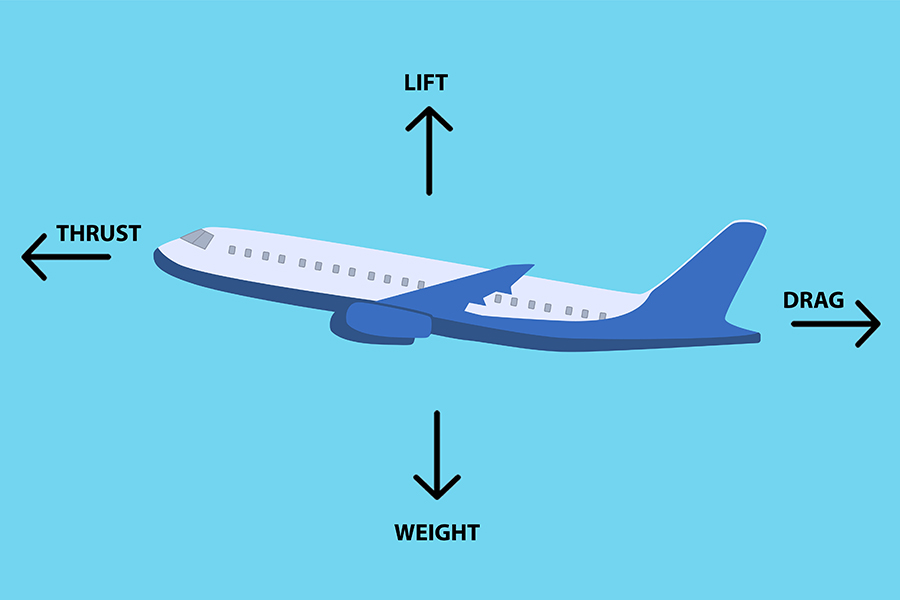
Airplane is lifting = Lift > Weight
Airplane moves forward = Thrust > Drag
Airfoils and Plane Structure and Lifting
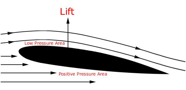
Airfoils generate an aerodynamic force by manipulating airflow. As air moves past the surface, the shape and angle of the structure cause the air moving over the top to travel faster than the air underneath, creating a pressure difference (lower pressure on top, higher pressure on the bottom) that results in an upward lift force.
Key geometric terms include:
- Chord line: A straight reference line connecting the leading (front) edge to the trailing (rear) edge.
- Camber: The asymmetry or curvature between the upper and lower surfaces of the airfoil.
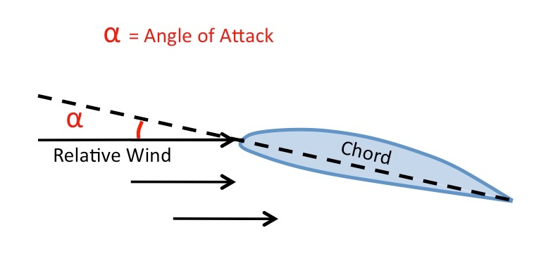
- Angle of Attack (AOA): The acute angle between the chord line and the direction of the oncoming airflow.
Wrong Lift Theories
1. The Equal Transit Time Theory
The equal transit time theory incorrectly claims that air traveling over the longer top surface of a wing must move faster than the air underneath so that separated air particles reach the trailing edge at the same time.
The Flaw: Air passing over the top of a wing actually moves much faster than predicted and reaches the back of the wing significantly earlier than the air moving underneath.
Why It Is False: As explained on the NASA Glenn Research Center site, molecules do not need to pair back up at the trailing edge, making this premise entirely false and as paper airplanes can fly despite having rectangular wings instead of fancy foils and having equal traveling molecule distance.
Bernoulli’s Principle
Bernoulli’s principle states that an increase in the speed of a fluid occurs simultaneously with a decrease in pressure or a decrease in the fluid’s potential energy. Although Bernoulli discovered that pressure decreases when the flow speed increases, it was actually Leonhard Euler who created Bernoulli’s equation.
Bernoulli’s principle can be derived from the principle of conservation of energy. This states in a steady flow, the sum of all forms of energy in a fluid will be the same at all points of that streamline. While all the energy remains constant, an increase in the speed of the fluid will imply there is an increase in the dynamic pressure (kinetic energy). This happens with a simultaneous decrease in the potential energy including the static pressure and internal energy.
Core Concept:
- As fluid (liquid or gas) speeds up, internal pressure drops.
- It represents the conservation of energy applied to fluid flow.
- Total mechanical energy along a streamline remains constant.
The Equation: The basic formula for an ideal fluid is:
p + (1/2) ρ v² + ρ g h = constant- p: Pressure exerted by the fluid
- v: Velocity of the fluid
- ρ: Density of the fluid
- h: Height/elevation
How does it apply on airplane wings: Airplane Wings: Air travels faster over the top of a wing than underneath, creating lower pressure on top and an upward lifting force.
Lift Force Equation (Physics): Simply Put
- F = ma
- or F = m (Δv/Δt) the force rate of change momentum.
To get Lift, we need to impact a change in momentum on the aircraft, and thus on the air (Newton’s Third Law), as we change the air direction velocity (as it is a vector force with a magnitude and direction) and in case of airfoils changing the direction of air generates (Lift Force).
Which moves faster: the wing through the air or the air past the wing?
The answer: it depends on your frame of reference. If your frame of reference is the airfoil, it will see that the airfoil is stationary and the air is moving past it, and if your frame of reference is away from the airfoil you might see that the air is stationary and the wing is moving through it. So you will find the answer actually is the SAME — they have the same speed. It is exactly the same as the air moving past the airfoil versus the airfoil moving through the air.
What Factors Affect Lift
- Object
- Motion
- Air
Object (The wing shape): you could find different shapes of wings like Rectangular wings and Swept wings, and different surface areas.
Motion: like the velocity of the air, angle of attack (AOA). The angle of attack is the angle at which relative wind meets an aerofoil. It is the angle formed by the chord of the aerofoil and the direction of the relative wind or the vector representing the relative motion between the aircraft and the atmosphere.
The Air (Air Viscosity): Air viscosity is defined as a measure of the resistance of air to flow, which affects the friction factor and flow characteristics in piping systems. It is expressed in absolute units of lb/ft·s.
- Dynamic viscosity (μ): This measures the internal friction between moving layers of air. At room temperature (15 °C), the dynamic viscosity of air is about 1.81 × 10⁻⁵ Pa·s.
- Kinematic viscosity (ν): This is the dynamic viscosity divided by the air density, showing how freely air moves under the force of gravity. At 15 °C, it is about 1.48 × 10⁻⁵ m²/s.
Structural and Aeroelastic Trade-offs
High-aspect-ratio wings yield high lift-to-drag ratios by minimizing induced drag; however, increasing wing length introduces significant structural flexibility. Under turbulent conditions or aerodynamic loads, flexible wings undergo severe bending moments and vibration, requiring active aeroelastic control systems to mitigate flutter and gust impacts without adding excessive structural weight.
“In gases, viscosity arises from molecules bumping into each other. When a gas is heated, the molecules move faster and collide more frequently and with more energy, causing the viscosity to increase.”
Why It Matters: Aerodynamic Drag: Air molecules stick slightly to the surface of moving objects (like airplanes or cars) to create a thin layer called a boundary layer. Viscosity and friction inside this layer create drag.
Calculating Lift (pretty hard thing to do)
It is pretty hard thing to do and there are a lot of equations and theories how to make it and we don’t really have a clear path how to do it. Here are some theories and the best one yet: Navier–Stokes equations.
Some theories:
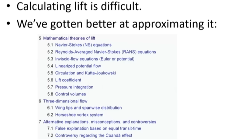
The Navier-Stokes equations are a set of mathematical formulas that describe how fluids — both liquids and gases — move.
Named after scientists Claude-Louis Navier and George Gabriel Stokes, these
equations work like Newton's second law (F=ma), but they apply to continuous
fluids rather than solid objects. They are used every day to model weather
patterns, ocean currents, and airflow around airplanes.
The Two Main Parts
The Navier-Stokes system has two primary rules:
- Conservation of Mass (Incompressibility): For everyday fluids like water, mass cannot be created or destroyed. Mathematically, this is written using divergence (∇ · u = 0), meaning the flow entering a tiny space must equal the flow leaving it.
- Conservation of Momentum (F=ma for fluids): Density times acceleration equals the sum of forces acting on the fluid.
Lift Equation approximating lift: The lift equation is a mathematical formula used to calculate the upward force generated by an aircraft wing moving through the air.
The Formula The NASA Lift Equation is written as:
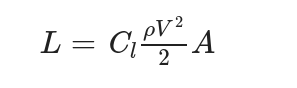
L = C_L · (1/2) ρ V² · A- (L): Lift force (in Newtons or pounds)
- (C_L): Lift coefficient (a number that shows how shape and angle affect lift)
- (ρ) (rho): Air density
- (V): Velocity or airspeed
- (A) or (S): Wing surface area
Lift: Lift depends on the density of the air, the square of the velocity, the air’s viscosity and compressibility, the surface area over which the air flows, the shape of the body, and the body’s inclination to the flow. In general, the dependence on body shape, inclination, air viscosity, and compressibility is very complex.
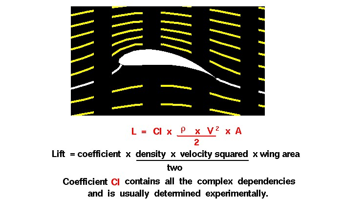
Key Components
- Lift Coefficient (C_L): Changes based on the angle of the wing against the wind (angle of attack) and the wing shape.
- Dynamic Pressure ((1/2) ρ V²): Combines air thickness (density) and speed. Speed has the biggest impact because it is squared; doubling your speed quadruples your lift.
- Wing Area (A): A larger wing surface creates more total lift.
Airfoils in DETAILS
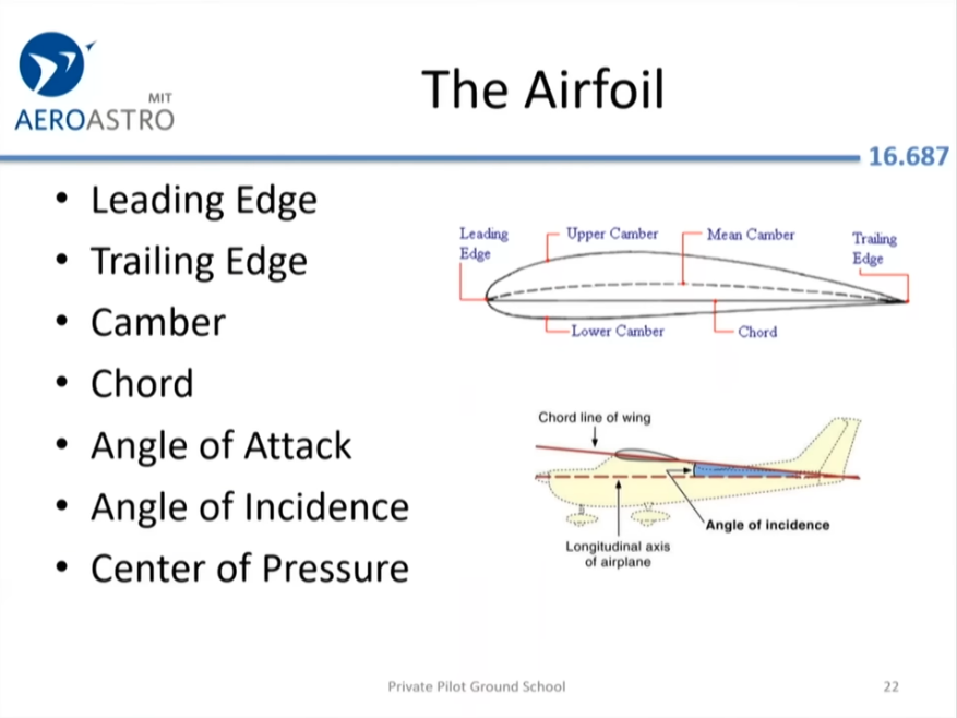
An airfoil is the cross-sectional shape of an aircraft wing, blade, or sail designed to produce more lift than drag when moved through the air.
Key Anatomy:
- Leading Edge: The front curve of the airfoil that first meets the oncoming air.
- Trailing Edge: The sharp rear edge where the separated air streams reunite.
- Chord Line: An imaginary straight line connecting the leading and trailing edges.
- Camber: The asymmetry or curvature between the upper and lower surfaces of the airfoil.
- Pressure Difference: As air splits around the wing, the flow over the top accelerates and creates a low-pressure zone, while the slower air underneath creates higher pressure.
“This pressure difference between the lower and upper surfaces creates lift.” — What Is an Airfoil? | How Wings Generate Lift.
- Symmetrical: Upper and lower curves match; used in aerobatic planes for stable inverted flight.
- Cambered (Asymmetric): Curved top and flatter bottom; generates lift even at zero angle of attack.
- Reflexed: Features an upward-curved trailing edge for specific pitch stability requirements.
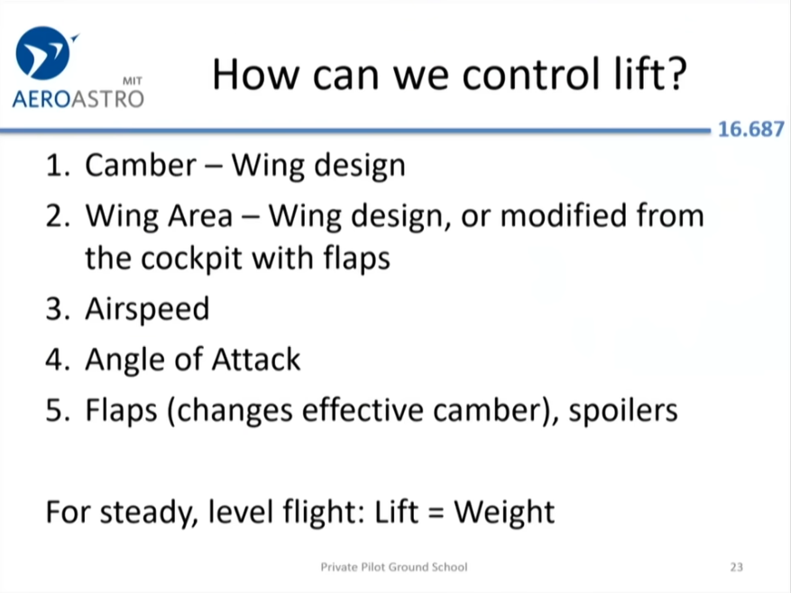
How can we control lift:
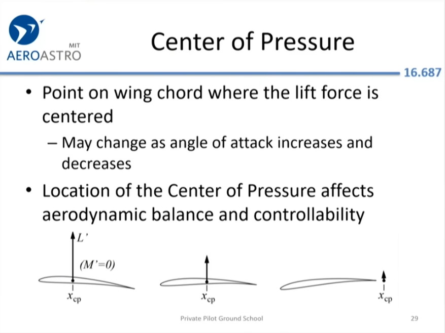
Center Of Pressure in an airfoil: The center of pressure (CP) on an airfoil is the specific point along the chord line where the total sum of all aerodynamic pressure and shear forces can be represented as a single resultant force with a pitching moment of zero.
Why It Matters in Aircraft Design:
- Stability: The position of the center of pressure relative to the aircraft’s center of gravity dictates pitch stability.
- Control: Because the CP moves as flight conditions and angles of attack vary, control surfaces (like elevators) must constantly compensate for changing aerodynamic moments to keep the aircraft stable.
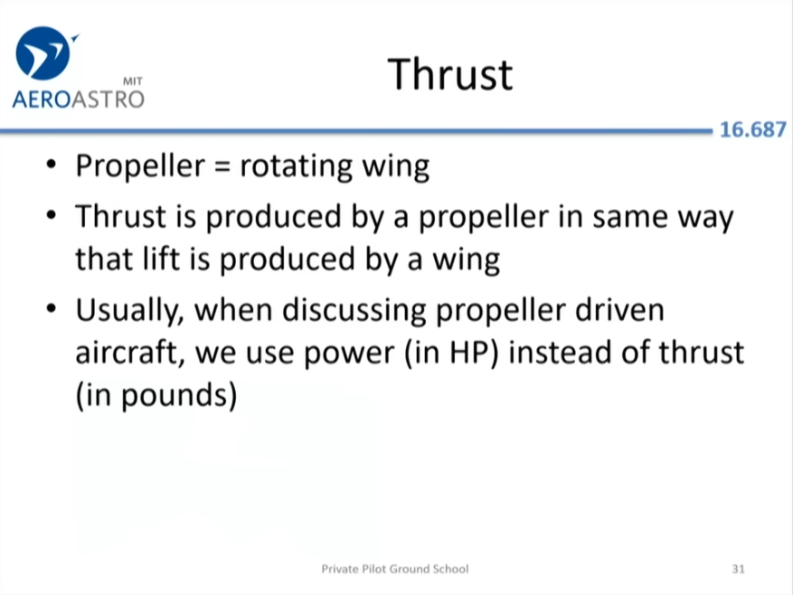
Thrust — The Forward force in an airplane: Thrust is the mechanical forward force produced by an airplane’s engines that propels the aircraft through the air and overcomes air resistance.
How Thrust Works:
- Engine Power: Propellers or jet engines create thrust by accelerating air or gas backward.
- Newton’s Third Law: When engines push air backward, an equal and opposite reaction pushes the airplane forward.
- Overcoming Drag: Thrust opposes drag (the backward retarding force of air resistance).
- Equilibrium: When thrust equals drag, the airplane moves at a constant speed. If thrust is greater, the plane accelerates.
According to WhiteBox Learning, “Thrust must overcome drag and produce enough velocity to achieve lift.”
Drag force in an airplane aerodynamics: Drag force is the mechanical aerodynamic force that pushes back on an airplane and opposes its motion through the air.
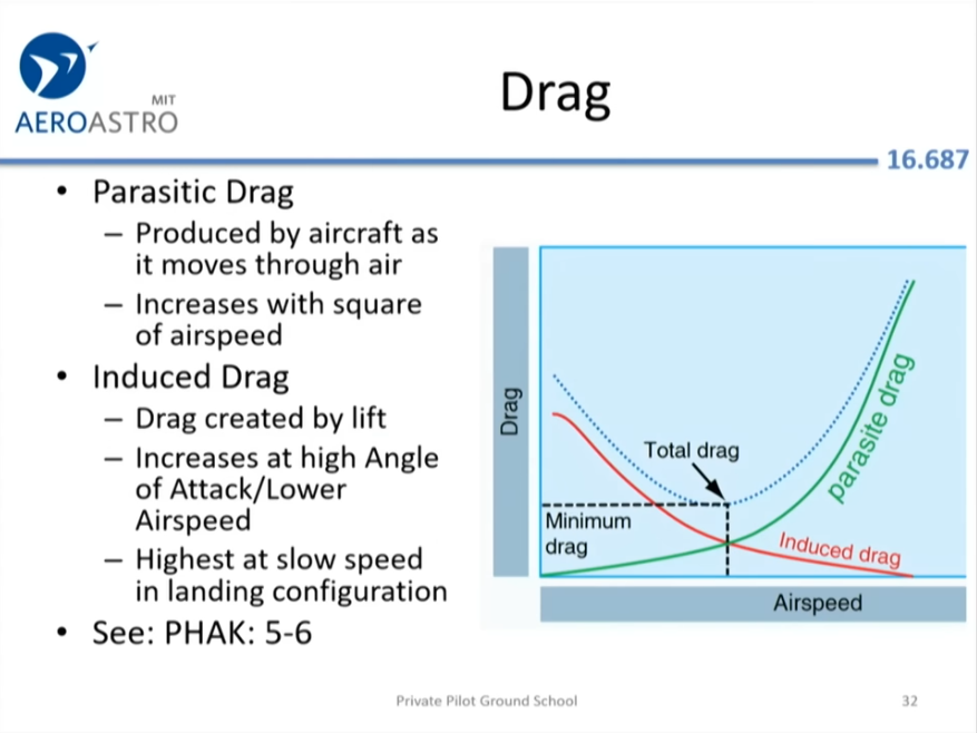
Total drag on an aircraft is split into two main groups: parasite drag and induced drag.
- Parasite Drag: This drag does not help create lift. It grows larger as the airplane goes faster. It includes:
- Form Drag: Caused by the shape of the plane and turbulent wakes.
- Skin Friction Drag: Caused by air rubbing against the smooth or rough outer skin of the aircraft.
- Interference Drag: Created when different airflows meet and clash, like where the wing joins the body.
- Induced Drag: This is a side effect of the wings making lift. It is highest at slow speeds and high angles (when the nose of the plane points high).
- Wave Drag: Happens near or past the speed of sound due to shock waves.
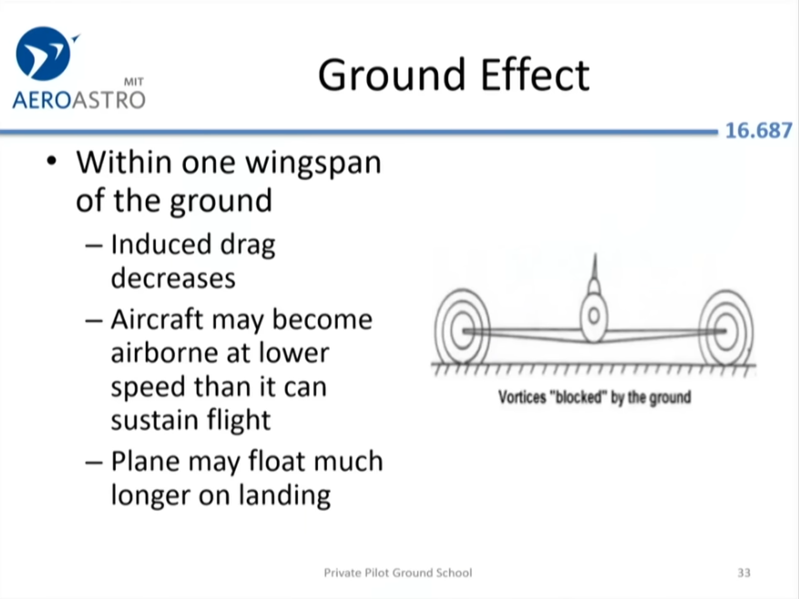
Ground Effect in an airplane: Ground effect is the name given to the positive influence on the lifting characteristics of the horizontal surfaces of an aircraft wing when it is close to the ground. This effect is a consequence of the distortion of the airflow below such surfaces attributable to the proximity of the ground. It applies to both fixed and rotary wing aircraft. Ground effect is also described as the reduction in induced drag when an aircraft flies close to the ground.
Why It Happens:
- Trapped Air: The ground blocks air from flowing downward.
- Cushion Created: This traps a cushion of high-pressure air under the wing.
- Vortices Blocked: The ground disrupts and shrinks wingtip vortices.
- Induced Drag Drops: Smaller vortices mean a massive reduction in induced drag.
Real-World Impacts:
- Early Takeoff: Planes can lift off before reaching safe climb speed.
- Floating: Planes may float down the runway during landing.
- Excess Speed: High approach speeds worsen the floating effect.
Critical Pilot Risks:
- Stall Hazard: Climbing out of ground effect too early can cause an immediate stall.
- Runway Overrun: Floating too long can cause the plane to run out of runway.
Historical Evolution of Flight
Wright Flyer (1903, The Wright Brothers)
The Wright Flyer (also known as the Kitty Hawk, Flyer I or the 1903 Flyer) made the first sustained flight by a manned heavier-than-air powered and controlled aircraft on December 17, 1903. Invented and flown by brothers Orville and Wilbur Wright, it marked the beginning of the pioneer era of aviation.
The aircraft is a single-place biplane design with anhedral (drooping) wings, front double elevator (a canard) and rear double rudder. It used a 12 horsepower (9 kilowatts) gasoline engine powering two pusher propellers. Employing ”wing warping”, it was relatively unstable and very difficult to fly.
The Wright brothers flew it four times in a location now part of the town of Kill Devil Hills, about 4 miles (6 kilometers) south of Kitty Hawk, North Carolina. The airplane flew 852 ft (260 m) on its fourth and final flight, but was damaged on landing, and wrecked minutes later when powerful gusts blew it over.
The brothers shipped the wreckage back to Dayton, and the aircraft never flew again. Orville later restored it and displayed it on several occasions. The Flyer joined the Smithsonian Institution’s collection of historic aircraft in 1948 after the end of a long and bitter dispute between Orville and the Institution over its refusal to recognize the Flyer as the first successful airplane. Today, it is on display in a place of honor in the National Air and Space Museum in Washington, D.C.
The Wright Brothers’ Iterative Breakthroughs (1900–1902)
While the 1903 Wright Flyer marked the first powered flight, its success relied heavily on rigorous experimental testing. In 1900, the Wrights tested a glider at Kitty Hawk featuring a forward horizontal surface (canard) for pitch control and flexible wingtips for roll control via wing warping. However, their 1901 glider produced only one-third of the lift predicted by contemporary aerodynamic tables, while generating significantly higher drag and stalling prematurely. Realizing existing data was inaccurate, they built a custom wind tunnel to test 100 to 200 small airfoil variations. This testing led to the 1902 glider, where they solved the issue of adverse yaw — the tendency of the nose to twist opposite to a roll — by integrating a movable rear rudder tied directly to the wing-warping system.
Commercial Milestones of the Mid-20th Century
Following the rapid adoption of the Douglas DC-3 in 1935 as a standard for long-distance commercial aviation, jet propulsion transformed aircraft design. In 1952, the BOAC Comet entered service as the world’s first commercial jetliner, cruising at 480 mph and establishing high-altitude, swept-wing transit for civil transport.
Aviation in World War I (1914–1918 WWI Advances)
World War I was the first major conflict involving the use of aircraft. Tethered observation balloons had already been employed in several wars and would be used extensively for artillery spotting. Germany employed Zeppelins for reconnaissance over the North Sea and Baltic Sea and also for strategic bombing raids over the Eastern Front and Britain.
Airplanes were just coming into military use at the outset of the war. Initially, they were used mostly for reconnaissance. Pilots and engineers learned from experience, leading to the development of many specialized types, including fighters, bombers, and trench strafers.
Ace fighter pilots were portrayed as modern knights, and many became celebrities back home. The war also saw the appointment of high-ranking officers to direct the belligerent nations’ air war efforts.
While the impact of airplanes on the course of the war was mainly tactical rather than strategic, the most important role being direct cooperation with ground forces (especially ranging and correcting artillery fire), the first steps in the strategic roles of aircraft in future wars were also foreshadowed.
Advent of the All-Metal Airplane (1930s Monoplanes)
By the early 1930s, aircraft design and construction technology throughout the world had advanced to the point where it was possible to mass-produce all-metal airplanes. There had been an all-metal plane as early as World War I, but it was an exception. Most airplanes of the war period and the 1920s had been primarily of wood and fabric construction, although many later ones had tubular steel fuselage frameworks.
The Air Corps’ first all-metal monoplane bomber was the Boeing B-9. Produced during 1932-1933, the B-9 was outclassed by its contemporary all-metal Martin B-10 and only seven were purchased. The Air Corps’ first all-metal monoplane fighter was the Consolidated P-25 of 1933. Although only two were procured, the P-25 design was modified into the P-30, later redesignated the PB-2, of which 54 were purchased in 1935. The first all-metal fighter ordered in quantity was the Boeing P-26; 139 were purchased from 1932-1936.
1940s (The Jet Age)
The Jet Age is a period in the history of aviation defined by the advent of aircraft powered by jet turbine engines and the social and cultural changes fostered by commercial jet travel.
Jet airliners were able to fly higher, faster, and farther than older piston‑powered propliners, making transcontinental and intercontinental travel considerably faster and easier. Aircraft leaving North America and crossing the Atlantic Ocean (and later, the Pacific Ocean) could now fly to their destinations non-stop, making much of the world accessible within a single day’s travel for the first time. Large jetliners could carry more passengers than piston-powered airliners, which caused air fares to decline and opened international travel to a broader range of socioeconomic groups.
In addition to pure jet engines, turbine-driven propeller engines delivered a smoother ride and better fuel efficiency. One exception to jet-powered domination by large airliners was the contra-rotating propellers turboprop design that powered the Tu-114 (first flight 1957). This airliner was able to match or even exceed the speed, capacity and range of contemporary jets, but such powerplants were only used in large airframes for military planes after 1976.
The introduction of the Concorde supersonic transport (SST) airliner to regular service in 1976 was expected to further revolutionize air travel by shortening travel times dramatically, but the aircraft never found commercial success. After two and a half decades of service, Concorde flights were discontinued in 2003 after a fatal crash near Paris in July 2000 and other factors. This was the only loss of an SST in civilian service. Only one other SST design was used in a civilian capacity, the Soviet era Tu-144, but it was soon withdrawn due to high maintenance and other issues. McDonnell Douglas, Lockheed and Boeing were three U.S. manufacturers that had originally planned to develop various SST designs since the 1960s, but these projects were eventually abandoned for various developmental, cost, and other practical reasons.
Supersonic aircraft (1969–1970s)
The first aircraft to achieve supersonic speed during its flight was the American Bell X-1 experimental plane, which was powered by a 6,000-pound (2,700 kg) thrust rocket powered by liquid oxygen and ethyl alcohol. Most supersonic aircraft have been military or experimental aircraft.
Aviation research during World War II led to the creation of the first rocket- and jet-powered aircraft. Several claims of breaking the sound barrier during the war subsequently emerged. However, the first recognized flight exceeding the speed of sound by a manned aircraft in controlled level flight was performed on October 14, 1947 by the experimental Bell X-1 research rocket plane piloted by Chuck Yeager. Moreover, the first aircraft to break the sound barrier with a female pilot was an F-86 Canadair Sabre with Jacqueline Cochran at the controls. According to David Masters, the DFS 346 prototype captured in Germany by the Soviets, after being released from a Boeing B-29 Superfortress heavy bomber at 32800 ft (10000 m), reached 683 mph (1100 km/h) late in 1951, which would have exceeded Mach 1 at that height. The pilot in these flights was the German Wolfgang Ziese.
On August 21, 1961, a Douglas DC-8-43 (registration N9604Z) exceeded Mach 1 in a controlled dive during a test flight at Edwards Air Force Base. The crew was composed of the following members: William Magruder (pilot), Paul Patten (copilot), Joseph Tomich (flight engineer), and Richard H. Edwards (flight test engineer). This was the first intentional supersonic flight by a civilian airliner, and the only one ever performed by a civilian airliner other than the Concorde or Tu-144.
In the 1960s and 1970s, multiple design studies for supersonic airliners were conducted and eventually two types entered service, the Soviet Tupolev Tu-144 (1968) and Anglo-French Concorde (1969). However, political, environmental, and economic obstacles, alongside one fatal Concorde crash, eventually prevented them from being utilized to their full commercial potential.
Modern Applications of Aerodynamics
- Commercial Aviation: Designing ultra-efficient wing shapes (supercritical airfoils) and adding winglets to reduce wingtip vortices, saving billions of gallons of fuel.
- Automotive & Motorsports: Formula 1 cars use inverted airfoils to generate downforce (negative lift), pushing tires onto the track for maximum grip at high speeds.
- Wind Energy: Modern wind turbine blades are giant, highly optimized airfoils designed to extract maximum kinetic energy from low-speed wind.
- Aerospace & Defense: Stealth technology utilizes faceted or blended-wing-body designs to minimize radar cross-sections while maintaining controlled aerodynamic stability.
The Future of Aviation
- eVTOL & Urban Air Mobility: Electric Vertical Takeoff and Landing vehicles using distributed electric propulsion for low-emission intra-city transport.
- Blended Wing Body (BWB): Merging the fuselage and wings into a single lifting body, offering up to 20% better fuel efficiency compared to conventional “tube-and-wing” designs.
- Sustainable Aviation Fuels (SAF) & Hydrogen: Transitioning engine combustion from fossil kerosene to zero-carbon energy sources without sacrificing high-thrust performance.
- Commercial Hypersonics: Aircraft designed to travel at speeds exceeding Mach 5 using scramjet engines, requiring advanced heat-resistant materials and complex high-speed fluid dynamics modeling.
Modern Experimental Wing Architectures & NASA Initiatives:
- Transonic Truss-Braced Wings (TTBW): Modern research focuses on ultra-high-aspect-ratio wings stabilized by diagonal structural struts. In 2026, NASA completed high-load structural testing on the 15-foot SWEET-15 truss-braced wing model, pushing it to 127% of its design limit load to evaluate joint behavior and structural boundaries.
- Active Aeroelastic Wings (AAW): Utilizing modified F/A-18 flight-test platforms, NASA investigated active aeroelastic control, twisting flexible wings during flight to control roll rather than relying solely on conventional hinged control surfaces — a modern evolution of the Wright brothers’ wing warping concepts.
- NASA AACES 2050 Program: Under the Advanced Aircraft Concepts for Environmental Sustainability initiative, NASA and industry partners are evaluating radical airframe-propulsion configurations — such as double-bubble lifting fuselages and blended wing bodies (BWB) — aiming for net-zero commercial aviation by 2050.
Resources & References
Fundamental Aerodynamics & NASA Resources
- NASA Beginner’s Guide to Aeronautics: Four Forces on an Airplane
- NASA Glenn Research Center: Incorrect Lift Theory #1 (Equal Transit)
- NASA Beginner’s Guide: Newton’s Laws of Motion
- NASA Glenn Research Center: Air Viscosity
- NASA Glenn Research Center: Air Properties & Temperature Effects
- NASA Glenn Research Center: Navier-Stokes Equations
- NASA Beginner’s Guide: The Lift Equation
- NASA Glenn Research Center: Center of Pressure
- NASA Glenn Research Center: Aerodynamic Drag
Airfoil Design & Dynamics
- Wikipedia: Airfoil
- Embry-Riddle Aeronautical University: Wing Shapes and Nomenclature
- Pilot Mall: 10 Types of Aircraft Wings Complete Guide
- National Aviation Academy: Airfoil Design
- Embry-Riddle Aeronautical University: Airfoil Geometries
- YouTube: What Is an Airfoil? | How Wings Generate Lift
Physics & Principles
- TecQuipment: Daniel Bernoulli, Bernoulli’s Principle and Equation
- Wikipedia: Bernoulli’s Principle
- ScienceDirect: Air Viscosity
- Wikipedia: Navier–Stokes Equations
- University of Manchester: Aeroelasticity and Structural Dynamics
Flight Control, Thrust & Drag
- SKYbrary: Angle of Attack (AOA)
- SKYbrary: Aerofoil
- SkyTeam Aviation: Thrust and Drag
- WhiteBox Learning: Glider Application & Thrust
- SKYbrary: Drag
- SKYbrary: Ground Effect
Aviation History & Milestones
- Wikipedia: Wright Flyer
- NASA Glenn Research Center: Wright 1901 Wind Tunnel Tests
- NASA Glenn Research Center: Wright Brothers Unpowered Aircraft (1900–1902)
- Wikipedia: Aviation in World War I
- National Museum of the US Air Force: Advent of the All-Metal Airplane
- Wikipedia: Douglas DC-3
- RAFMuseum: de Havilland Comet Enters Service
- Wikipedia: Jet Age
- Wikipedia: Supersonic Aircraft
Future Concepts & Advanced NASA Initiatives
- Northrop Grumman: Blended Wing Body Aircraft
- Mansoura Engineering Journal: Sustainable Aviation Fuels (SAF) Research
- NASA Aeronautics: Commercial Hypersonic Flight Testing
- NASA Image Article: Transonic Truss-Braced Wing (TTBW) Research
- NASA Reference: Active Aeroelastic Wing (AAW) Research
- NASA Reference: Advanced Aircraft Concepts for Environmental Sustainability (AACES 2050)